JA-80V
Service explanation for JA-80V
1 Installation in the control panel
If you purchased the communicator separately, it should be installed in the Oasis control panel as follows:
) Thecontrol panel's power supply should be off (both 220V and the emergency battery)
) Place the communicator in the control panel in the right place and use the supplied screws to secure the communicator. Connect the communicator to the control panel using the digital bus cable.
c) Connect the PSTN cable to the telephone line - the telephone must support CLIP (EN 300 089 V3.1.1) protocol with caller ID and SMS in text must be enabled. (Contact your provider for more information.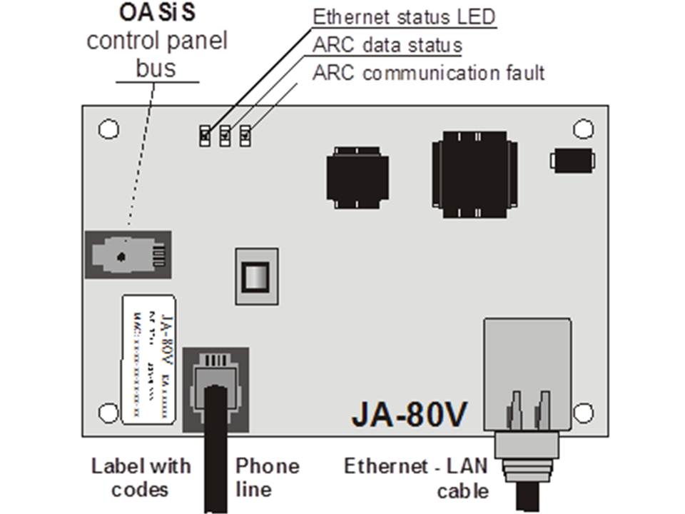
2 Activating the communicator for the first time
If the communicator is installed in the control panel then:
) Have a LAN (Ethernet) cable ready
) Turn on the power to the control panel (220V and battery). The communicator's green LED should come on = no events to report to an ARC.
c) If your LAN network is not set up with a DHCP server, program the Ethernet network parameters manually. (see 5.16).
d) Connect the LAN cable (10/100 Mbit). If communication with the network is correct, the yellow LED will light up continuously.
If the LED starts flashing check the DHCP parameters, if the LED goes out after 3 seconds of flashing the communicator is not connected to the Ethernet at all.
) If communication to an ARC is desired, the ARC parameters should be set according to the ARC's specifications
) Close the control panel housing
3 communicator functions for the user
The following text describes the functions available to the user. The installer should instruct the user how to use these functions in a particular installation
3.1 Temporarily authorizing the keypad of a telephone as a control panel for the system
It is possible to control the system via a temporarily authorized telephone. This is done as follows:
a) dial the number of the system
b) After 25 seconds of ringing (adjustable) the system answers with a short beep
c) key in a valid access code on the phone (e.g. 8080 or 1234 if the factory settings are still valid)
d) the keypad of the phone now functions as a control panel an audio signal will indicate the status of the system: 1 beep = Enabled, 2x beep = Disabled, 3x beep = Service mode, 4x beep = invalid entry, siren = alarm
e) the system can now be operated from the phone in the same way as from a control panel - including commands beginning with * (e.g. *81 to activate the PGX output)
) To exit this mode then disconnect (if there is no entry for 1 minute the connection is automatically disconnected by the PBX)
Notes:
§ do not go too fast when entering, each key needs time to be sent and processed.
§ A landline phone can also be used in the same way.(the phone must use tone dialing)
§ Each time the connection is made, the phone must be re-authorized with the code mentioned earlier because the phone is only authorized during the connection to the system.
3.2 SMS instruction set for remote control system
The phone line connected to the PBX is used to receive SMS messages on it but must support the CLIP protocol for sending and receiving SMS messages in text format to take advantage of this feature. The SMS message parameters must be set. See 5.10 and 5.11.
All incoming SMS messages are checked by the communicator for instructions to the system and these are then executed. Each instruction must satisfy the following conditions: code instruction (valid code space instruction)
valid code = a valid system code (e.g. 8080, 1234 etc.)
The default instruction set from the factory (configurable - see 5.3
)| Instruction | Function | Note |
| SET | Enable | Enable and disable in the same way as a code is keyed on the control panel. If the system is already in the desired mode, nothing changes. |
| UNSET | Disable | Turn on and off in the same way as a code is entered on the control panel. If the system is already in the desired mode, nothing changes. |
| STATUS | Request status | Including ARC communication (displayed as MS1 and MS2). |
| MEMORY | Request last action | The last action in the central controller memory. |
| PGX ON | Turn PGX on | The PG outputs must be programmed for the function: on/off (with 237/247) or 2 second switching (with 238/248) |
| PGX OFF | Turns PGX off | The PG outputs must be programmed for the function: on/off (with 237/247) or 2 second switching (with 238/248) |
| PGY ON | Switch PGY ON | The PG outputs must be programmed for the function: on/off (with 237/247) or 2 second switching (with 238/248) |
| PGY OFF | Turn PGY off | The PG outputs must be programmed for the function: on/off (with 237/247) or 2 second switching (with 238/248) |
Example: sending the instruction "code SET" (valid code space SET) will turn the system on (if it is already on nothing happens
)Notes:
§ Execution of the instruction is confirmed with an SMS message
§ The instructions are not case sensitive and only ASCII characters are allowed
§ An SMS message can contain only one instruction
§ Enabling and disabling by an instruction starting with a service code only works if the option for enabling and disabling by service code is set in the control panel. (to prevent unauthorized activation and deactivation by installers.
§ If there is other text in the message not separated by a "%" the instruction will not be executed.
§ If you send a message and you are not sure if the provider adds extra text send the instruction as follows: %code instruction%%%
§ No other SMS receiving device can be connected to the same telephone line as the communicator.
3.3 Free operation of the system through missed calls from pre-programmed numbers
If the phone line supports CLIP protocol and number recognition then a limited number of instructions can be performed remotely by calling the system from an authorized phone and ending the call before the system picks up the line. In this way, the system can be operated free of charge with a limited number of functions. It is possible to authorize numbers stored in memory M1 to M8 (also used as warning numbers see 4).
To authorize a phone number place * after the number followed by one digit (1,2,3,8 or 9) - See note in section 4.
If a call is made by that number the communicator will generate "* digit" after the first ring. (As if manually keyed in on the control panel). This free control of the system with unanswered calls can include the following functions according to which digit is after the * in the memory:
*1 Enable complete system (= ABC button on control panel)
*2 Enable section A (= A button)*
*3 Enable section A and B or B (= B button)*
*8 PGX on for 2 seconds. (If the PGX is programmed for the pulse function)
*9 PGY on for 2 seconds. (If the PGY is programmed for the pulse function)
Note:
§ If the phone rings with number lock, it cannot be used to operate the system in this way
§ If the call is terminated before the dialer answers, this function is free.
§ A phone that has this free function can also fully operate the system once the communicator has picked up and a valid code has been entered (see 3.3). Let the phone ring until the communicator picks up the line.
§ If the number programmed for free control does not need to receive system reports, disable reports for this number (see 5.2).
§ Enabling with *1, *2 and *3 only works if it is activated in the control panel.
4 Reporting to phone
The communicator can report system actions by SMS and/or calling numbers with a sound signal. Reports can be sent to up to 8 numbers.
The most common reports are already set up from the factory, you only need to program the numbers in the place that contains the correct settings. If required, other operations can also be added or deleted. (see 5.2)
Default settings for numbers M1 to M8
| M | Reports |
| 1 | Alarms and errors via SMS |
| 2 | |
| 3 | Alarm and errors via SMS + calling (if you answer you will hear a siren) |
| 4 | |
| 5 | Alarm via SMS + ringing, switching on and off and errors via SMS only |
| 6 | |
| 7 | Alarm via ringing (when you answer you will hear a siren) |
| 8 | Technical error SMS (e.g. for installer) |
To program a phone number in one of the memory locations M, key in the following sequence when the system is in service mode: 81 M xxx...x *0
Where:
M memory location 1 through 8
xxx....x phone number (up to 20 digits)
Example: By keying 81 5 777 777 777 *0 the number 777777777 will be stored in memory location 5 (Alarm via SMS + calling, enable and disable and errors via SMS only)
To remove and number from location M key: 81 M *0
Note:
§ entering *9 before the number generates a "+" for programming an international number
§ If desired, actions can be sent to a connected SMS phone (SMS8010), program number 001 in the memory.
§ SMS report consists of: Installation name, action name, number and name of origin (device or code), date and time.
Example: "Report from your Alarm: enabled 47: code Time 01.08. 11:27".
§ If other actions or text should be reported to a specific number, change the setting in the communicator (see 5.2 and 5.3)
§ When entering phone numbers, if you enter *7 after the last digit of the phone number (the * is also stored) and then add one more digit (1,2,3,8 or 9), this number can call the system. The system then responds as if "* digit" was keyed in after the first ring. In other words, as if it was manually keyed in on the control panel. - see section 3.3. Example: entering 81 5 777 777 777 *79 *0 has the number 777777777 can turn on the PGY output for 2 seconds just by calling the system and ringing 1 time. The system then responds as if *9 was keyed in on the control panel. This can be used, for example, to open an automatic door or gate.
4.1 Programming
The easiest way of programming is by means of a PC with the ComLink software or via the Internet on the page: www.gsmlink.cz
Programming is also possible on the control panel:
§ The control panel must be in service mode, if not key in *0 Service code (default: 8080) while the system is switched off.
§ Key in the relevant programming sequences - See table below.
To exit service mode press the # key
5.1 Programming telephone numbers for reporting to telephones
See chapter 4.
5.2 Selection of reporting to be sent to phones
The default list of call forwarding and associated position in memory M1 to M8 can be changed as follows.
- The complete list of possible call forwarding is shown in the table below.
- It is possible to select whether a call forwarding is via SMS only, via call only or and SMS followed by a call.
- Each call forwarding has its own default SMS text. These texts can be customized (see 5.3). The sound of the siren during a call cannot be adjusted (e.g. an alarm situation is indicated by a siren when you pick up the phone)
5.2.1 Setting actions forwarded to a specific number via SMS.
To link actions to reports via SMS key: 82 ec M x
Where:
ec code of the action 01 to 32 (see table above)
Phone number at memory location 1 to 8
0
= no SMS report, 1 = yes SMS report
Example: If 82 03 8 1 is programmed and a smoke alarm goes off (event 03 in the table), the communicator will send an SMS report to the number at memory location M8
.5.2.2 Setting operations forwarded to a specific number via a call
To link operations to reports via a call key: 83 ec M x
Where:
ec code of the operation 01 to 32 (see table above)
Phone number at memory location 1 to 8
0
= no call, 1 = call
Example: if 82 03 1 1 is programmed and a smoke alarm goes off (event 03 in the table), the communicator will send a call to the number at memory location M1, if the call is accepted a siren will be heard his.
Note:
§ Alarm via call is most commonly used as an audio alert to allow the user to read the detailed SMS report.
§ If both SMS and call are used the SMS will be sent first, then the call. Reporting to an ARC goes before anything else if it is active. (see 7.1 )
5.3 Changing SMS text
The communicator contains several pieces of text to generate an SMS report as well as an SMS instruction set. These texts cannot be changed on the control panel but can be changed with the ComLink software, via the Internet (www.GSMLink.cz) or by sending the following SMS instruction: code_TXT_n,text,n,text,......n,text
Where:
code is a valid code (e.g. default codes 8080, 1234)
_ is a space
TXT Instruction to change text
n Text number (0 to 611 see next table)
, comma (or end)
text The new text (max. 30 characters) which will overwrite the old text. It is not allowed to use a comma or an ending in the new text, a space is allowed.
Note:
§ A single TXT instruction can change multiple texts (limited by the maximum length of a single SMS)
§ The communicator is not case sensitive and it is recommended to use only English ASCII characters. (some networks do not accept non-English characters)
§ The communicator creates an SMS with 5 parts: Installation name, operation description, source (code or device) number (01 to 50), source name, time and date.
§ The maximum length of an ASCII SMS is 160 characters (70 characters for national characters). If this length is exceeded the communicator will divide the report over several SMS messages.
Examples: if the service code is 8080 then the following instruction: 8080 TXT 20,Remote control Peter,21,Remote control Karin will be the description (name) of the remote controls at address 20 and 21.
8080 TXT 605,heating on,606,heating off changes the 2 instructions used to switch the heating using the PGX output (It must be programmed den as on/off.
- The communicator always automatically puts the numbers 01 to 50 in front of the device name or code.
- Texts 0 to 532 are used to create and SMS report
- Texts 601 to 11 are SMS instructions (to use the system remotely via SMS)
- Text 419 is for internal use of the communicator, never change!
5
.4 Set up reporting to a phone
Reports can be set up in the following way:
800 All SMS and call reporting All SMS and call reporting enabled
802 All reporting enabled except reporting of turning on and off by users 41 to 50 (including codes, cards and remote controls). This allows to disable reporting to recipients of reporting (users, boss etc.).
803 All SMS and call reporting on if ARC1 does not respond
804 All SMS and call reporting on if ARC2 does not respond
Default setting: 801 All reporting enabled
5.5 Phone number for direct remote access
A phone number programmed with this sequence has immediate access to the system regardless of the setting on incoming calls. When this number rings, the system answers after the first ring (the phone line must support CLIP protocol and number recognition) 902 xx...x *0
Where:
xx...x = phone number
Note:
- If remote access is disabled (see 5.6), then using this number for remote access is also disabled.
Default setting: removed
5.6 Remote Access
Remote access (by phone or over the Internet) can be turned on or off:
9030 Disabled
9031 Enabled
Default setting: Enabled
5.7 Forwarding of incoming SMS messages
This option allows forwarding of incoming SMS messages that do not contain valid instructions to the communicator:
9260 messages are not forwarded, the communicator does send them via CLIP protocol to the simulated telephone line.
Messages are forwarded to the first never in memory M1 to M8 (e.g. if there is only a number programmed in memory location M6 and M7 then the message will be sent to the number in location M6) The number from which the original message was sent will be appended to the beginning of the message.
Default setting: Messages are forwarded
5.8 Reaction to incoming calls
The communicator's reaction to incoming calls can be set as follows: 904 x
Where:
= 0 Incoming calls ignored
= 1 to 8 The communicator answers after x times 5 seconds of ringing (e.g. x=4=20sec.)
= 9 Answer the second call - first it has to ring at least once, then a pause (10 to 45 seconds) and then after the first ringing of the second time the communicator will answer the call
.Default setting: 935 - answered after 25sec (about 5 rings)
5.9 Initializing GSMLink communication
After successfully connecting the communicator to the LAN network, the code 913 can be typed in order to connect to the server of www.gsmlink.cz (the server will register the IP address of the communicator).
In order to remotely control the system via the Internet, it is necessary to make a registration on the site www.gsmlink.cz (after the communication has been initialized) To register the system (see 7.5) you need the registration code printed on the label on the communicator
Note:
- The communicator periodically reports to the GSMLink server to dor the current IP address to the server's database. (The time between 2 reports is shorter according to the use of the GSMLink website). If you try to access it through the website after the communicator's dynamic IP address has been changed, you will get a message that the server is waiting for the next report from the communicator To shorten this time, you can enter the above code (913) on the control panel while the system is in service mode. You can also do this remotely by calling the communicator using a phone whose number is stored in the communicator for this purpose. (See below).
5.9.1 Phone number for initialization of GSMLink communications
GSMLink communications can be initialized remotely by calling from the number programmed as follows:
914xx...x *0
Where:
xx...x
phone number (max. 20 digits
)Note:
- After the first ring from the number programmed as above, the communicator will send a report with the current IP address to the GSMLink server.
- This method of remote initialization works only if the phone line to the communicator supports CLIP number recognition).
Default setting: removed
5.10 Tx SMS central phone number
To send SMS messages via the CLIP protocol over the telephone line it is necessary to program the Tx SMS central phone number by:
942xx...x *0
Where:
xx...x
Tx SMS central phone number
Note:
- Contact your provider to ask what the Tx SMS central phone number is.
Default setting: removed
5.11 Rx SMS central phone number
To receive SMS messages using the CLIP protocol it is necessary to program the Rx SMS central phone number by:
942xx...x *0
Where:
xx...x = Rx SMS central phone number
Note:
- Contact your provider to ask what the Rx SMS central phone number is.
- Also check how to activate SMS messages vis text (Some providers translate the SMS message to a voice call).
Default setting: removed
5.12 Testing reporting to an ARC
To test reporting to an ARC press:
961a where a = ARC number (1 or 2
)Note:
The operation "communication test" (ec=31) will be sent to the specified ARC. The green LED flashes during the communication, if the red LED goes out it indicates that the communication to the ARC has failed.
5.13 Testing call to a phone number
To test if the communicator is able to call a phone number stored in memory key:
962M
Where
The phone number is in memory location 1 to 8
If location M contains a phone number, the communicator will call this number. If the call is answered an audio signal will be heard.
5.14 Activate re-login to LAN
After entering the code 935, the communicator will log out of the network and re-login (DHCP refresh).
5.15 Communicator reset
With the code 98080 the communicator will fall back to all factory settings. All texts, phone numbers and ARC settings are thus back to default.
5.16 Automatic DHCP
The default setting in the communicator ensures that after connection the communicator automatically requests a network address from the DHCP server in the LAN network. If you want to enter an address manually you should disable the automatic DHCP setting, as described below, and set the P address manually, as described below, before connecting to the network.
9300
DHCPdisabled
9301
enabled
Default setting: Enabled
5.17 communicator IP address
If DHCP is disabled (see 5.16), the communicator IP address can be set as follows
:931 xxx xxx xxx xxx xxx
Where:
...x is the IP address
Example: If the IP address is 192.168.1.23 key: 931 192 168 001 023
Default setting: 192.168.001.211
5.18 Network Mask
If DHCP is disabled (see 5.16) program the network mask as follows:
932 x32xxx xxx xxx xxx
where:
...x is the network mask
Example: If the network mask is 255.255.255.0 key: 932 255 255 255 000
Default setting: 255.255.255.000
5.19 Network gateway address
If DHCP is disabled (see 5.16) program the network gateway address as follows:
933xxx xxx xxx xxx xxx
Where:
...x is the gateway address
Example: If the gateway address is192.168.33.1 key: 933 192 168 033 001
Default setting: 192.168.001.001
5.20 DNS IP address
If DHCP is disabled (see 5.16) program the DNS address as follows:
934xxx xxx xxx xxx
Where:
...x is the DNS address
Example: If the DNS address is 192.168.33.1 key: 933 192 168 033 001
Default setting: 192.168.001.001
5.21 ARC Phone Numbers / IP Addresses
Reporting can be sent to up to 2 ARCs (independently or ARC2 an serve as backup to ARC1) Each ARC has a main number and a backup number (or IP address) These can be set up with:
Main: 01 a xx....x *0
Backup: 02 a xx....x *0
Where:
1=ARC1
, 2=ARC2
...x tel. number (max. 20 digits)
or IP address and port - example:
01 2 *8 192 168 001 123 08080 *0
where *8 (Translated to a #) to indicate an IP address. An IP address must have 12 digits and must be followed by a 5 digit port number (no spaces)
To delete a number/IP address key: 01p*0 or 02p*0
If the numbers/IP addresses of an ARC are deleted no more reports will be sent to that ARC
Notes:
- The communicator always tries to send data to the main number first, if this fails then the backup number is used.
- IP CID is a fast protocol and allows very regular monitoring of communications to an ARC (e.g. Every 5 minutes)
- The contact ID protocol an be used to report to an ARC over the telephone line. (If they support the Contact ID protocol)
- If your ARC does not support IP CID protocol, contact your Jablotron distributor to upgrade your ARC.
- Another way to do backup communication to an ARC is to have it call a specific phone number (see 5.2). This way, 8 groups can send notifications to an ARC. For this you need an ARC with 8 phone lines and number recognition. By calling a certain number on the ARC, the communicator communicates the group of notifications to the ARC because the ARC knows which number it is being called on. Through number recognition, the ARC knows who the notification is coming from. The ARC does not answer the line so this type of notification is free. Using this method, the ARC gene sends confirmation back to the communicator that the notification was successfully received.
Default setting: All tel. numbers and IP addresses removed
5.22 Installation (alarm system) ID for ARC
The installation ID number is sent to the ARC with each report and can be programmed by: 03 a zz..z *0
Where:
1=ARC1
, 2=ARC2
..z installation ID number, max. 8 characters (0 to 9 and *1=A to *6=F - hexadecimal number
)Default setting: 0000 for both ARCs
5.23 Selection of events sent to ARCs
The system recognizes 32 different types of events, see table below. This setting determines which event is sent to which ARC.
05 a ec x
Where:
1
= ARC1, 2 = ARC2
ec event code 01 to 32
0
= no report, 1 = report
5.24 Delay for resending data to an ARC
The communicator first tries to send a report to the main number / IP address, if this fails then it immediately tries the backup number / IP address. If this also fails then the communicator makes a complete new attempt to send the data to both ARCs. The time between 2 attempts can be set by: 06 a x
Where:
1
= ARC1, 2 = ARC2
is the delay: 0=immediate, 1 to 9 = 1 to 9 minutes
Default setting: 1 min. for both ARCs
5.25 ARC communication check interval
The waiting time after the last report has been sent that a communication check should be performed. The communication check event code is 31 (see Error! Reference source not found.). This sequence sets how often a check will be performed: 07 a uumm
Where:
1
= ARC1, 2 = ARC2
hours
mm minutes
Notes:
- Monitoring reports are not sent in service mode
- IP CID protocol allows very regular monitoring to an ARC (e.g., every 5 minutes).
Default setting:24 hours after the last report - for both ARCs
5.26 Enable ARC reporting (ARC2 is backup for ARC1)
This setting allows the reporting to ARC1 or ARC2 to be set and whether ARC2 is a backup for ARC1: 00 a x
Where:
1=ARC1
, 2=ARC2
0=off
, 1=on, 2= ARC2 is a backup for ARC1 (2 can only be entered at ARC2
)Note:
If ARC is a backup to ARC1, data will only go to ARC2 if the forwarding to ARC1 has failed. ARC2 will also get an additional report "Communication error to ARC1" in addition to the already existing reports to send.
Default setting: both ARCs = off
5.27 Store reports sent to ARCs in memory
This option activates that each successful report to any ARC is stored in internal memory.
080 enabled
081 disabled
Note:
It is recommended to disable this option. This saves a lot of space in the control panel's internal memory. However, ARC communication errors can then be stored because it can be assumed that each message was sent successfully. If it is not successfully sent within 110 seconds of the attempt, it will be reported and stored in memory (see 5.28).
Default setting: enabled
5.28 Indication of an ARC communication error if a report is not successfully sent after 110 seconds of initiation.
Enables the indication and reporting of a communication error of a failed report within 110 seconds of commencement of sending to an ARC.
communication error do not report
091 communication error report
Note:
- The communicator continues the attempt to deliver the notification to the ARC even after a communication error is displayed. (if the data is delivered then the communication error indication stops)
- For communication control the maximum delivery time (confirmation from the ARC) is 300 minutes. For any other notification, the notification must be acknowledged by the ARC within 110 seconds after the notification starts (if not, a communication error is generated)
Default setting: communication error indication not enabled
5.29 Locking ARC settings
All settings that affect reporting to an ARC can be locked with a digital code: 901 xx..x *0
Where:
xx..x Code entered by the installer (4 to 8 digits
Notes:
- upon exiting service mode after entering a code, all settings related to ARC communication will be locked. (See the list in section 5).
- If ARC programming is locked, it can be temporarily unlocked by entering the code: 901 xx..x *0 where xx..x is the lock code. After exiting service mode the settings are locked again.
- ARC settings can be permanently unlocked by entering the sequence: 901*0 while ARC settings are temporarily unlocked - see above. This will unlock them.
Factory default setting: ARC settings unlocked
6 LAN network configuration
Each device in an Ethernet network (LAN, Internet) has its own IP address (e.g. 192.168.250.20). This address can be a public address or a private address. Before connecting the Ethernet cable, the correct setting must be entered - by automatic DHCP or manually (see 5.16).
§ If automatic DHCP is selected, contact the network administrator and ask them to prepare the network to connect the communicator. If the administrator needs the MAC address it is on the sticker on the communicator.
§ Manual programming of the network parameters should preferably be done by a network administrator who knows how to set them
7.1 How the communicator sends reports
Once a report is to be sent (e.g. in the case of an alarm) the
communicator
will send a report to the alarm center. On an alarm) the communicator will:§ send the data to ARC1, if in use (the communicator tries the main number / IP address first, if unsuccessful then the backup number / IP address).
§ Then the communicator sends the data to ARC2 in the same way as it is programmed as an independent ARC. If ARC2 in set as a backup to ARC1 then ARC2 will only be used if notification to ARC1 has failed.
§ Then the communicator sends an SMS report (1st number, 2nd number .... 8th number)
§ Then the communicator will make calls (1st number, 2nd number .... 8th number) - each number is called only 1 time whether the call is answered or not.
§ If previous attempts to send data to ARCs has failed then after the set time another and attempt will be made. (see 5.24).
If the alarm is stopped by a user SMS and call reporting will be aborted, notifications but ARCs will always continue and are always completed to all ARCs.
7.2 The communicator LEDs
Green LED:
§ Blinking regularly - Communication in progress (ARC, SMS or remote access)
§ off - data queued before being sent to an ARC
§ Constantly on - no data queued to be sent to an ARC
Red LED:
§ off - Communication with an ARC is OK
§ constantly on - impossible to send data to an ARC
Yellow LED:
§ flashing regularly - Ethernet connected, DHCP not working
§ off - Ethernet is not connected
§ constantly on - Ethernet is connected and communication net the network is OK
7.3 After entering the service code, the communicator will:
- Complete reports to ARCs (if required)
§ Unfinished SMS and calls will be aborted
§ Unsent ARC reports will be deleted only if the ARCs phone number / IP address, ARC communication setting or installation ID code is changed.
§
Alarm recovery and error recovery reports are sent to the ARCs in service mode
§ Changes to the settings only take effect once service mode is exited
7.4 Configuring the communicator in user mode
If configuration in user mode is enabled, the following settings can be changed:
- tel. numbers M1 to M7
The events reported by SMS and call
7.5 remote control via the Internet
The system can be remotely controlled via www.gsmlink.cz which allows complete system setup by an installer or management by a user. To do this it is necessary to:
- Connect the communicator to the Ethernet network which allows access to www.gsmlink.cz
- Register the communicator via the GSMLink web page by:
o Open the www.gsmlink.cz page and select New registration
o Create your own user name and password
o Enter the communicator's registration code. (see Error! Reference source not found.)
o Enter the phone number of the SIM card
o Enter a valid master or service code (for the user or installer menu)
o After setting the above data, there should be connection to the system
If your communicator uses dynamic IP addresses while communicating with the GSMLink server, you may have to wait for connection (if the IP address has changed). GSMLink indicates how long YOU have to wait until connection is re-established. To reduce the waiting time, it is possible to remotely establish the connection to call the system with a device programmed for this purpose. (see 5.9.1).
- For future sessions you only need to enter your user name and password (they can also be remembered by your web browser)
- multiple people can register the communicator for remote management (users in installers)
- A service technician only needs to have one set of login credentials to manage multiple systems. After the first system is registered, the mechanic add or remove systems from his or her GSMLink account.
- There is a demo version for remote management www.gsmlink.cz
- using www.gsmlink.com is free of charge